Quick start guide
Hardware requirements
To run the demo application, you need the following hardware:
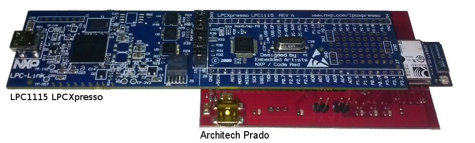
- LPC1115 LPCXpresso Board
- Architech Prado daughterboard
- 802.11b/g-compliant Wi-Fi access point with internet access
- Two Jumper
- Two mini usb cables
- A pc/laptop with Windows operating system and a WiFi device
- 2 male strip (1x20) to soldier in LPCXpresso Board
- A UART interface (3,3V level only) to connect Prado to your pc. This interface is not provided.
Software Requirements
- A Registered version of “Free LPCXpresso IDE” at the least version 5.2.4: http://lpcxpresso.code-red-tech.com/LPCXpresso/. You need create an account and register the product.
- Source of demo: SILICA site
- Terminal emulator application such as Hyperterminal or other with UART support.
Note
You will use the terminal emulator to send configuration commands to the module over a UART interface. The emulator also displays information transmitted from the module.
Set Up Software
- Install the IDE LPCExpresso and following the instructions of default
- Launch LPCExpresso and select a workspace folder
- In the menu go to Help → Product activation → Create serial number and activate. Follow the instructions to register the software
- When you will have an activation code go to Help → Enter Activate Code
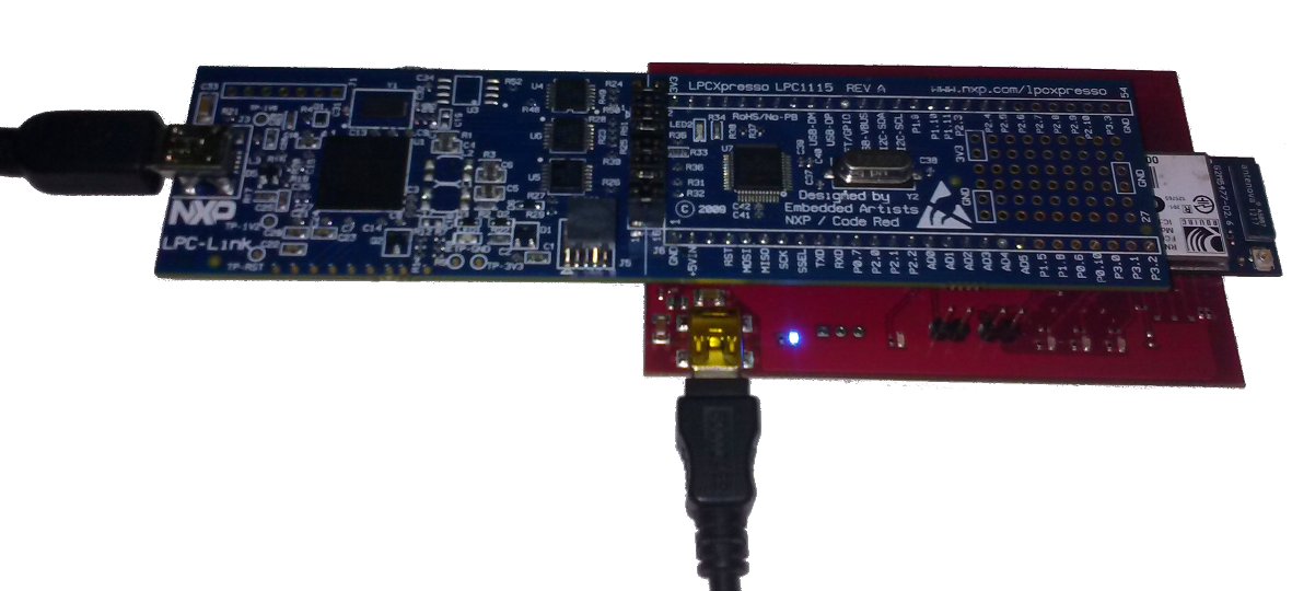
Set Up Hardware
Perform the following steps to set up the hardware and prepare it for configuration:
- In LPCXpresso Board connect J4 PIN1 to J4 PIN2, J4 PIN3 to J4 PIN4, ... J4 PIN15 to J4 PIN16.
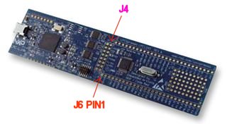
- solder two male strip (1x20) on the LPCxpresso board in:
J6 from PIN1 (GND) to PIN20 (AD5)
J6 from PIN28 (3V3) to PIN47 (P2.5)
- Mount the LPC1115 LPCXpresso Board connectors on Prado evaluation board. LPCXpresso J6 PIN1 must be connect in Prado U1 PIN1 ... J6 PIN20 to U1 PIN20 ... J6 PIN47 to U1 PIN40 ... J6 PIN28 to U1 PIN21.
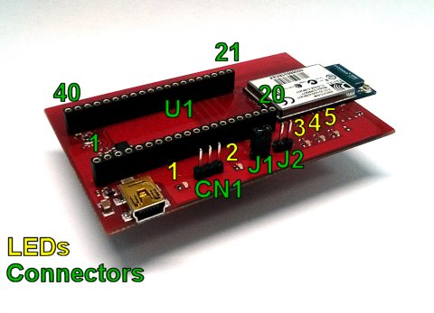
- remove the two jumpers J1 and J2 from Prado
- Connect PC to boards with mini-USB cables.
- Optionally connect the UART interface (not provided) from the connector Prado CN1 (UART 3,3V level only) to the PC if you want see the communication between the LPC1115 and the WiFi module. The UART configuration is Baud: 9600, Data: 8bit, Parity: None, 1bit stop, Flow: None
PIN1 = LPC_UART_RX (3,3V level)
PIN2 = LPC_UART_TX (3,3V level)
PIN3 = GND
- make sure that the router is connected to internet and it is configured to accept the connection of the module RN-131C and it can access the internet. Router must have:
- A secure Wi-Fi authentication schemes (WEP / WPA / WPA2).
- DHCP enabled
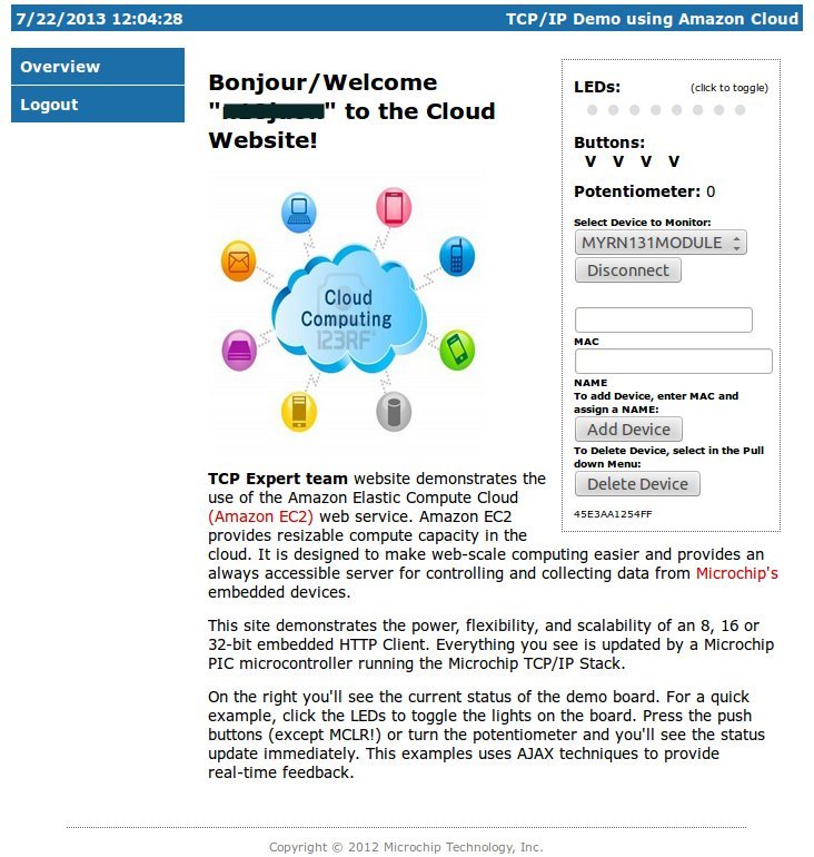
Microchip Demo
- Register the module to the Microchip website:
- Browse to the website: http://mtt.mchpcloud.com and follow the instructions on the page to create an account.

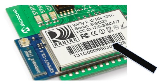
- Logging in with the account that you have created and follow the instructions to register the MAC address of the module. Associate to a name, such as MYRN131MODULE. Later this name will be used to connect the demo server to the cloud. The MAC address of the module are the last few 6-hex bytes in the numerical sequence shown under the barcode module.
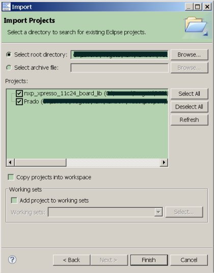
2. Importing the demo into your LPCXpresso workspace To use the projects in LPCXpresso, they must first be imported into LPCXpresso. To import the projects, go to File → Import → General → Existing Projects and press Next. On the import dialog window in the Select root directory box, browse to the platform directory lpcopen/applications/lpc11xx/xpresso_projects/nxp_xpresso_11c24/. Select nxp_xpresso_11c24_board_lib and Prado. Make sure the Copy projects to workspace option is disabled. Then select Finish to start the import.
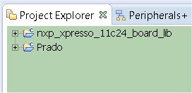
The imported project should appear in the Project Browser window.
- Compile it by selecting from the menu Project → Build → Build All. If the compilation fails, for all node in Project Explorer window open the properties form and go to Settings → Include and modify the relative paths in absolutes. Then retry to compile.
Run demo first time
- Choose Prado in project explorer and launch debugging by pressing the icon showed below:

then once the progam is been uploaded, press:

2. All messages of the demo will be displayed on the debug console LPCXpresso IDE, see options.h for details. After initialization, the dispositive will try to associate with an Access Point within 10 seconds. The message associating ... will appear on the debug console. In this state only LED2 blinks.
3. After 10 seconds if it fails to join the demo will set the module as an Access Point (SOFT AP). Once set, appear the message on the debug console Config w / Browser http://5.16.71.1. In this state, the demo application will work as a small webserver, blue LED2 blinks and red LED4 and LED5 are turned on.
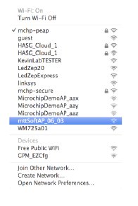
4. The demo in this state, it is waiting for a connection request from a browser. As an Access Point, the module’s IP address is 5.16.71.1. Its SSID is mttSoftAP_xx_yy, where xx & yy, are the last two hex bytes of the module’s MAC address (example mttSoftAP_03_06). Associate your PC to this access point.
- The module is listening for TCP address, open a browser (IE, Safari, Firefox) etc, and enter http://5.16.71.1:2000/index.html into the browser window.
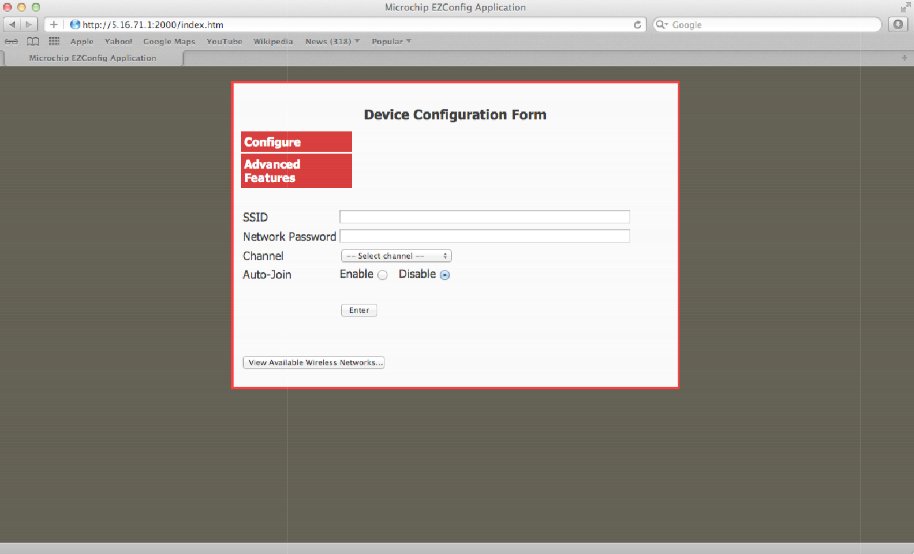
- Insert in all areas, the SSID of the access point where the RN-131C can connect to access of internet, Password (appears in plain text), select a channel, and enable channel auto-join. After that click on the Enter button.
7. Now that the demo has all the information to access the Access Point sets the WIFI module with all the data and try to access. It is important that there are no filters on the network that prevent the module to access the internet otherwise the demo can not continue. If happen, fix the configuration router and restart the application.
8. Set the PC to access the access point and go with the company http://mtt.mchpcloud.com browser to the site. Log in and select the name chosen previously, for example MYRN131MODULE. Press the Connect button to enable communication between the module and the WiFly cloud server. Once connected you will see on the website the data transmitted from the demo. In this state if all works correctly you will see all leds LED1, LED2, LED3, LED4 turned on and LED5 blinking slowly.